1. Rangkaian Audio Amplifier 100 Watt
adalah rangkaian elektronika yang berfungsi memperkuat sinyal audio
yang masih lemah sehingga bisa asyik didengar oleh kita. Audio
amplifier nyaris terdapat pada hampir semua perangkat elektronika audio
visual. Jika Anda ingin memperkuat sinyal audio pada perangkat audio
visual Anda, cobalah gunakan / tambahkan audio amplifier ini. Apalagi
bila Anda suka mendengarkan musik so pasti Anda ingin mendengarkan suara
musik yang mantap di telinga.
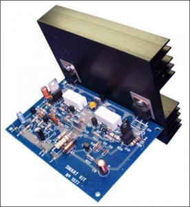
Rangkaian audio amplifier mungkin sudah
tidak asing lagi bagi Anda yang fan audio dan sudah banyak tersebar di
internet dan buku-buku, tapi Rangkaian Audio Amplifier 100 Watt
ini jelas beda dengan yang pernah Anda lihat / baca. Untuk lebih
jelasnya bisa Anda lihat dan pelajari gambar skemanya di bawah ini.
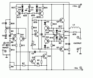
R1 = 1,2 Kilo Ohm
R2 = 0,47 Ohm
R3 = 220 Ohm
R4 = 3,9 Kilo Ohm
R5 = 2,2 Kilo Ohm
R6 = 2,2 Kilo Ohm
R7 = 10 Kilo Ohm
R8 = 4,7 Kilo Ohm
R9 = 150 Ohm
R10 = 39 Ohm
R11 = 3,3 Kilo Ohm
R12 = 10 Kilo Ohm
R13 = 4,7 Ohm
R14 = 1 Ohm
R15 = 39 Ohm
R16 = 1 Ohm
R17 = 220 Ohm
R18 = 22 Ohm
R19 = 1,2 Kilo Ohm
R20 = 10 Kilo Ohm
R21 = 220 Ohm
R22 = 680 Ohm
R23 = 3,9 Kilo Ohm
R24 = 18 Kilo Ohm
R25 = 100 Ohm
R26 = 18 Kilo Ohm
R27 = 680 Ohm
R28 = 1,2 Kilo Ohm
P1 = 1 Kilo Ohm
D1 = 1N4002-7
D2 = 1N4002-7
D3 = 1N4148
D4 = 1N4148
D5 = 1N4148
D6 = 1N4148
D7 = 1N4148
D8 = 1N4148
Q1 = BDW84D
Q2 = BD829
Q3 = BC546
Q4 = BC556
Q5 = BC556
Q6 = BC556
Q7 = BC548
Q8 = BC546
Q9 = BDW83D
Q10 = BD830
Q11 = BC556
C1 = 10uF/63V
C2 = 33pF
C3 = 270pF
C4 = 100nF
C5 = 2,2uF/63V
C6 = 100uF/35V
C7 = 120pF
C8 = 100nF
C9 = 10uF/63V
2. Rangkaian Pengusir Tikus
 .
.Daftar komponen Rangkaian Pengusir Tikus elektronika:
R1 … 1K
R2,R3 … 15K
C1 … 1nF
C2 … 1uF/16V
C3 … 10nF
C4 … 220nF
C5 … 1000uF/16V
D1..D4 … 1N 4001
IC1 … 555
Tr1 … Trafo 6V/200mA
TD1 … speaker tweeter bentuk corong
F1 … Fuse/sekring 50 mA
Rangkaian Pengusir Tikus Elektronik adalah sebuah oscilator yang mengeluarkan gelombang ultrasonic pada kisaran frekuensi 20 – 40 KHz. Gelombang ultrasonic yang dihasilkannya tidak akan terdengar di telinga kita tapi akan sangat mengganggu sekali bagi telinga tikus.
Untuk menghindari tikus menjadi kebal terhadap Rangkaian Pengusir Tikus Elektronik, maka Base Frequency dimodulir dengan signal 50 Hz yang didapat dari frekuensi tegangan jala-jala PLN melalui kapasitor C4 sehingga akan dihasilkan ayunan frekuensi antara 20 – 40 KHz secara periodik. Efek yang dialami tikus akan terasa sangat dasyat, seolah-olah seperti kita berada pada sebuah konser music amburadul dengan irama yang acak-acakan dan tidak bisa dinikmati sama sekali, plus sa’at itu kita lagi sakit gigi!! Bisa dibayangkan, music trust-metal mungkin masih jauh lebih indah dibanding suara alat ini
Jantung rangkaian pengusir tikus elektronik adalah sebuah IC tipe 555. Gunakan loudspeaker dari piezo electric atau speaker tweeter bentuk corong agar frekuensi ultrasonic-nya lebih nendang dan efektif. Pengusir tikus elektronik ini efektif untuk ruangan seluas maksimal 200 m2 asal penempatannya tepat. Bisa diletakkan di pojok atas ruangan agar frekuensi noise-nya bisa menyebar ke seluruh ruangan tanpa halangan. Nyalakan secara terus menerus untuk menjaga agar tikus tidak datang lagi, tidak usah khawatir dengan konsumsi listriknya karena daya listrik yang dibutuhkan cukup rendah, masih lebih besar lampu bohlam 5 watt/220 volt. Pengaturan frekuensi dsb. tidak diperlukan pada Rangkaian Pengusir Tikus Elektronik ini.
3. Skema Saklar On-Off Digital | Saklar On-Off Digital
ini merupakan saklar yang bekerja untuk menghubungkan arus listrik dan
memutus arus listrik dari sumbernya. Cara kerja dari rangkaian ini
adalah, apabila pada switch on/off ditekan maka relay akan tertutup atau
dalam kodisi on, dan jika ditekan kembali maka relay akan terbuka atau
memutus aliran listrik ke kondisi off.
Rangkaian ini sangat sederhana hanya terdiri dari beberapa komponen. Anda bisa menggabungkan atau menerapkan aplikasi rangkaian ini misalnya ke peralatan Audio (amplifier) yang pernah anda rakit sebelumnya ataupun diaplikasikan untuk peralatan elektronik lainnya, sehingga anda tidak lagi menggunakan saklar manual, lebih kereeen khan ?...
Pada umumya peralatan elektronika modern saat ini sudah tidak banyak yang dioperasikan secara manual (saklar manual) dan tergeser oleh peralatan elektronika yang dioperasikan digital. Rangkaian saklar on/off dibawah ini adalah salah satu contoh operasi digital :
 | ||
| Skema Rangkaian Saklar On-Off Digital |
4. Rangkaian Elektronika Pengusir Nyamuk
Rangkaian elektronika pengusir nyamuk yang saya berikan ini termasuk dalam rangkaian elektronika yang sederhana. Karena kesederhanaannya inilah yang membuatnya mudah untuk dipelajari bagi seorang pemula sekalipun. Selain itu, untuk membuatnya tidak diperlukan biaya tinggi alias sangat murah. Namun demikian aplikasi dari rangkaian ini tentunya tetap sangat bermanfaat dalam kehidupan sehari-hari kita yaitu mengusir nyamuk dari rumah kita. Bahkan dengan alat ini kita juga dapat menggunakannya diluar ruangan, semisal ketika ngeronda ataupun sekedar santai di halaman.
Selain sebagai pengusir nyamuk, rangkaian ini juga bisa digunakan pada jenis serangga ataupun jenis binatang penggangu lainnya. Contohnya adalah pada kecoa dan tikus. Prinsip utama bagaimana rangkaian ini bekerja adalah dengan berdasarkan bahwa serangga atau jenis binatang pengganggu lainnya sangatlah sensitif kepada beberapa frekuensi suara, terutama frekuensi suara yang tinggi. Dengan demikian, disaat rangkaian ini dihidupkan akan membuat jenis-jenis hewan tersebut merasa terganggu dan menjauhkan diri dari alat ini. Berbeda dengan manusia yang tidak dapat mendengar frekuensi suara yang tinggi, maka tentunya tidak akan menyebabkan gangguan suara bagi kita yang berada didekatnya sekalipun.
Untuk gambar dari rangkaian elektronika pengusir nyamuk sendiri, banyak rupanya. Namun saya coba pilihkan yang paling menarik untuk dicoba aplikasikan yaitu bekerjanya secara otomatis karena dikendalikan oleh Light Depending Resistor/ LDR. Alat ini akan menyala dengan sendirinya bila berada di lokasi yang gelap, dan sebaliknya akan mati bila dilokasi terang. Dengan begini alat akan otomatis bekerja jika lampu kamar kita dimatikan.
Perlu diingat kembali ya bahwa rangkaian ini menggunakan speaker untuk mengeluarkan frekuensi yang sama dikeluarkan oleh nyamuk jantan. Pada waktu bukannya musim untuk kawin, maka nyamuk betina akan menjauhi frekuensi ini. Dengan begitu nyamuk betina yang menghisap darah tidak akan ada disekitar alat ini, sedangkan nyamuk jantan memang tidak menghisap darah. Namun pada musim kawin yang terjadi adalah sebaliknya yaitu nyamuk akan tertarik untuk mendekatinya. Karena itu pilih-pilih saja waktu yang tepat. Oh iya, bila diperdalam lagi mengenai nyamuk maka nyamuk tidak memiliki mata. Mereka berkomunikasi memakai antena yang ada dikepalanya untuk menangkap frekuensi disekitarnya. Selengkapnya bisa disimak pada rangkaian dibawah ini:

Komponen yang diperlukan dari rangkaian diatas adalah N1, N2, N3 = IC4011 dengan transistor tipe NPN biasa. Kemudian C1 = 100mkro Farad, C2=100nf, dan C3=10nf. Nah, silahkan dicoba ya Rangkaian Elektronika Pengusir Nyamuk ini
5. RANKAIAN ELEKTRONIKA SWITCH INFRA MERAH

saklar infra merah switch.dengan alat ini berfungsi untuk mendeteksi sinar infra merah yang di pancarkan remot control sehingga alat ini dapat berfungsi sebagai saklar dengan bantuan relay untuk menghubungkan beban listrik apa bila anda berminat hubungi saya.
6. MEMBUAT LAY OUT RANGKAIAN PADA PCB DENGAN TEKNIK PEMINDAHAN TONER
Yang dimaksud teknik pemindahan toner,
adalah teknik membuat PCB dengan cara memindahkan gambar lay out atas
sebuah rangkaian dari kertas glosi (kertas majalah) ke PCB polos pada
sisi tembaga. Gambar lay out atas rangkaian pada kertas glosi pindah ke
PCB polos (sisi tembaga) menjadi lay out bawah. Sebetulnya yang
berpindah adalah toner-toner yang membentuk gambar lay out atas pada
kertas, karena pengaruh pemanasan.
Sedang untuk membuat lay out rangkaian membutuhkan software bantu Eagle 4.11.
Berikut ini adalah cara membuat lay out rangkaian pada PCB dengan teknik pemindahan toner :
1) Cetak lay out atas rangkaian pada kertas majalah (glosi).
2) Gunakan printer toner seperti laser jet. Printer tinta tidak dapat digunakan untuk proses ini. Jika tidak memiliki printer toner, cetak gambar di atas kertas putih, kemudian gambar difoto kopi di atas kertas majalah, atau kalender, atau kertas foto, atau plastik transparan.
3) Untuk membuat lay out atas rangkaian gunakan program bantu seperti Eagle, atau DipTrace, atau PCB Artist.
4) Potong lay out atas yang sudah dicetak pada kertas dengan ukuran tepi 3 mm.
5) Potong PCB polos seukuran lay out atas.
6) Amplas atau kikir bagian tepi P CB polos hingga halus.
Foto oleh Xaveria dan Lenny
7) Bersihkan permukaan PCB sisi tembaga dengan amplas halus di bawah keran air.
Foto oleh Xaveria dan Lenny
8) Keringkan PCB, dan siapkan setrika listrik serta alas kain atau kertas putih.
9) Letakkan PCB diatas alas kain atau kertas polos dengan sisi tembaga menghadap ke atas. Taruh potongan kertas lay out atas rangkaian di atas PCB, dengan gambar menghadap sisi tembaga PCB.
10) Lapisi bagian atas potongan kertas dengan kain atau kertas putih. Agar sewaktu disetrika, gambar pada potongan kertas (majalah) tidak menempel pada setrika.
11) Tekan setrika di atas tumpukan PCB, gambar lay out atas, dan kain (kertas putih) selama 30 detik. Ini dilakukan agar gambar menempel pada sisi tembaga PCB.

Foto oleh Xaveria dan Lenny
12) Gosok setrika hingga merata pada seluruh permukaan PCB, khususnya bagian tepi PCB selama lebih kurang 4 menit.
13) Diamkan PCB hingga termperaturnya kembali normal.

Foto oleh Xaveria dan Lenny
14) Masukkan PCB ke dalam air, rendam lebih kurang 5 menit (untuk kertas majalah); untuk bahan kertas yang lebih tebal seperti kalender atau kertas foto, perendaman lebih kurang 10 hingga 15 menit.
15) Cabut atau lepaskan kertas majalah yang menempel pada PCB. Bersihkan bagian jalur yang masih bersinggungan atau lubang kaki komponen dengan cara digosok-gosok.

Foto oleh Xaveria dan Lenny
Sedang untuk membuat lay out rangkaian membutuhkan software bantu Eagle 4.11.
Berikut ini adalah cara membuat lay out rangkaian pada PCB dengan teknik pemindahan toner :
1) Cetak lay out atas rangkaian pada kertas majalah (glosi).
2) Gunakan printer toner seperti laser jet. Printer tinta tidak dapat digunakan untuk proses ini. Jika tidak memiliki printer toner, cetak gambar di atas kertas putih, kemudian gambar difoto kopi di atas kertas majalah, atau kalender, atau kertas foto, atau plastik transparan.
3) Untuk membuat lay out atas rangkaian gunakan program bantu seperti Eagle, atau DipTrace, atau PCB Artist.
4) Potong lay out atas yang sudah dicetak pada kertas dengan ukuran tepi 3 mm.
5) Potong PCB polos seukuran lay out atas.
6) Amplas atau kikir bagian tepi P
 CB polos hingga halus.
Foto oleh Xaveria dan Lenny
7) Bersihkan permukaan PCB sisi
 tembaga dengan amplas halus di bawah keran air.
Foto oleh Xaveria dan Lenny
8) Keringkan PCB, dan siapkan setrika listrik serta alas kain atau kertas putih.
9) Letakkan PCB diatas alas kain atau kertas polos dengan sisi tembaga menghadap ke atas. Taruh potongan kertas lay out atas rangkaian di atas PCB, dengan gambar menghadap sisi tembaga PCB.
10) Lapisi bagian atas potongan kertas dengan kain atau kertas putih. Agar sewaktu disetrika, gambar pada potongan kertas (majalah) tidak menempel pada setrika.
11) Tekan setrika di atas tumpukan PCB, gambar lay out atas, dan kain (kertas putih) selama 30 detik. Ini dilakukan agar gambar menempel pada sisi tembaga PCB.

Foto oleh Xaveria dan Lenny
12) Gosok setrika hingga merata pada seluruh permukaan PCB, khususnya bagian tepi PCB selama lebih kurang 4 menit.
13) Diamkan PCB hingga termperaturnya kembali normal.

Foto oleh Xaveria dan Lenny
14) Masukkan PCB ke dalam air, rendam lebih kurang 5 menit (untuk kertas majalah); untuk bahan kertas yang lebih tebal seperti kalender atau kertas foto, perendaman lebih kurang 10 hingga 15 menit.
15) Cabut atau lepaskan kertas majalah yang menempel pada PCB. Bersihkan bagian jalur yang masih bersinggungan atau lubang kaki komponen dengan cara digosok-gosok.

Foto oleh Xaveria dan Lenny
Hal-hal yang perlu diperhatikan sebelum membuat papan nama dari susunan LED,
1) Gunakan LED bening.
2) Warnai bagian atas PCB dengan warna gelap (hitam).
3) Perhatikan spesifikasi LED. Pada percobaan ini gunakan LED bening diameter 5mm
yang memancarkan warna merah, spesifikasi tegangannya sebesar 3 volt.
Cara pemasangan LED :
1) Satu huruf tersusun paling banyak 5 kolom dan 7 row.
2) Satu kolom paling banyak tersusun oleh 6 LED yang diseri.
3) Kemudian kelima kolom dihubung secara paralel.
4) Setiap kolom diberi hambatan, Rx, yang besarnya tergantung pada banyaknya LED dalam satu kolom dan tergantung juga pada jenis LED (pada percobaan ini LED yang digunakan berdiameter 5mm, bening dengan pancaran cahaya merah).
5) Pada kolom yang terdiri dari 6 LED, Rx = 330 ohm; 5 LED, Rx = 560 ohm; 4 LED, Rx=680 ohm
Ingat, ketentuan ini berlaku untuk 5 mm LED bening pancaran cahaya merah.
6) Setiap huruf diberi penguat transistor FCS9013.
Berikut adalah skema satu huruf LED.

Sedang gambar di bawah ini adalah lay out atas papan nama 2 huruf. Untuk membuat papan nama 8 huruf, tinggal disalin dari yang 2 huruf ini.
 Berikut ini adalah lay out bawahnya.

Contoh susunan LED pada hur uf A dan B :
Nilai Rx pada kolom pertama dan kelima (huruf A) sebesar 560 ohm, karena terdiri dari 5 LED yang tersusun seri. Rx pada kolom kedua, ketiga, dan keempat, sebesar 680 ohm karena terdiri dari 2 LED.
Rx kolom pertama huruf B, 330 ohm. Rx kolom kedua, ketiga, keempat, dan kelima sebesar 680 ohm.
Selamat mencoba ! Semoga SUKSES !
Kalau ada kesulitan bisa dibagikan di forum ini !
1) Gunakan LED bening.
2) Warnai bagian atas PCB dengan warna gelap (hitam).
3) Perhatikan spesifikasi LED. Pada percobaan ini gunakan LED bening diameter 5mm
yang memancarkan warna merah, spesifikasi tegangannya sebesar 3 volt.
Cara pemasangan LED :
1) Satu huruf tersusun paling banyak 5 kolom dan 7 row.
2) Satu kolom paling banyak tersusun oleh 6 LED yang diseri.
3) Kemudian kelima kolom dihubung secara paralel.
4) Setiap kolom diberi hambatan, Rx, yang besarnya tergantung pada banyaknya LED dalam satu kolom dan tergantung juga pada jenis LED (pada percobaan ini LED yang digunakan berdiameter 5mm, bening dengan pancaran cahaya merah).
5) Pada kolom yang terdiri dari 6 LED, Rx = 330 ohm; 5 LED, Rx = 560 ohm; 4 LED, Rx=680 ohm
Ingat, ketentuan ini berlaku untuk 5 mm LED bening pancaran cahaya merah.
6) Setiap huruf diberi penguat transistor FCS9013.
Berikut adalah skema satu huruf LED.
Sedang gambar di bawah ini adalah lay out atas papan nama 2 huruf. Untuk membuat papan nama 8 huruf, tinggal disalin dari yang 2 huruf ini.
Berikut ini adalah lay out bawahnya.
Contoh susunan LED pada hur
 uf A dan B :
Nilai Rx pada kolom pertama dan kelima (huruf A) sebesar 560 ohm, karena terdiri dari 5 LED yang tersusun seri. Rx pada kolom kedua, ketiga, dan keempat, sebesar 680 ohm karena terdiri dari 2 LED.
Rx kolom pertama huruf B, 330 ohm. Rx kolom kedua, ketiga, keempat, dan kelima sebesar 680 ohm.
Selamat mencoba ! Semoga SUKSES !
Kalau ada kesulitan bisa dibagikan di forum ini !

Rangkaian
8 LED berjalan adalah dasar untuk membuat 8 huruf LED. Sedikit berbeda
dengan running LED dengan IC 4017 (decade counter), 8 running led ini
menyala secara bergiliran, tetapi yang sudah nyala sebelumnya tidak mati
ketika led setelahnya menyala. 8 led akan mati setelah led ke-8
menyala. Sedang pada running led (decade counter), sistem nyala led
seperti "titik", hanya ada satu led yang menyala di antara kesepuluh
led.
Komponen
utama adalah IC 74LS164 (SHIFT REGISTER), dengan pewaktunya adalah
rangkaian astable multivibrator (menggunakan IC NE555).
Rangkaian
akan lebih berdaya guna bila menggunakan catu daya yang stabil
(regulator) dengan menggunakan IC Regulator 7805. Dibawah ini skema
rangkaian catu daya stabil 5 volt dc.
 Gambar
di bawah ini adalah lay out atas dan lay out bawah rangkaian 8 LED
Berjalan, lengkap rangkaian catu daya stabil 5 vdc untuk rangkaian 8 LED
Berjalan dan 15 vdc untuk rangkaian 8 huruf LED.
Gambar
di bawah ini adalah lay out atas dan lay out bawah rangkaian 8 LED
Berjalan, lengkap rangkaian catu daya stabil 5 vdc untuk rangkaian 8 LED
Berjalan dan 15 vdc untuk rangkaian 8 huruf LED.

9. Rangkaian Astabil Multivibrator
Komponen utama rangkaian ini adalah IC 555 (timer). R1 dan C1 adalah komponen yang berperan sebagai pembentuk frekuensi gelombang persegi yang dihasilkan oleh rangkaian astabil.
Bentuk persamaannya :
 Dibawah ini adalah rangkaian astabil dengan komponen utama IC 555 (ada astabil yang dibangun dari IC 4093 (schmitt trigger)).
Penghitung Digital Menggunakan 74LS90
 Adalah
rangkaian penghitung maju 0 s.d 9 dengan IC 74LS90 sebagai komponen
utama. Jika pada kaki-kaki input IC (12, 8, 9, 11) berlogika 0, maka
pada seven segment akan tampil angka 0. Rangkaian ini secara kontinu
menghitung angka mulai dari 0 sampai 9, lalu kembali ke 0 dst.
Adalah
rangkaian penghitung maju 0 s.d 9 dengan IC 74LS90 sebagai komponen
utama. Jika pada kaki-kaki input IC (12, 8, 9, 11) berlogika 0, maka
pada seven segment akan tampil angka 0. Rangkaian ini secara kontinu
menghitung angka mulai dari 0 sampai 9, lalu kembali ke 0 dst.
 Rangkaian
ini sangat sederhana, hanya terdiri dari sebuah IC (74LS47), 7 buah
resistor (150 ohm s.d 470 ohm) dan sebuah seven segment. Sangat cocok
bagi siswa, mahasiswa teknik elektronika (tingkat 1), maupun hobis
pemula.
Rangkaian
ini sangat sederhana, hanya terdiri dari sebuah IC (74LS47), 7 buah
resistor (150 ohm s.d 470 ohm) dan sebuah seven segment. Sangat cocok
bagi siswa, mahasiswa teknik elektronika (tingkat 1), maupun hobis
pemula.Di bawah ini adalah susunan kaki pada seven segment common anoda (ca).

Angka 0 ditampilkan seven segment, jika input D (kaki 6), C (kaki 2), B (kaki 1), A (kaki 7) dihubung ke ground (jalur negatif bater). Atau dapat dikatakan secara digital D C B A = 0000.
12. Rangkaian LED Berjalan
Komponen utama rangkaian ini adalah IC 4017 yang memiliki 10 keluaran (kaki 3, 2, 4, 7, 10, 1, 5, 6, 9, 11). LED akan menyala satu per satu (model dot). IC 4017 membutuhnya detak yang berasal dari rangkaian astabil.
Komponen utama rangkaian ini adalah IC 4017 yang memiliki 10 keluaran (kaki 3, 2, 4, 7, 10, 1, 5, 6, 9, 11). LED akan menyala satu per satu (model dot). IC 4017 membutuhnya detak yang berasal dari rangkaian astabil.
Skema Rangkaian LED Berjalan


Kita
dapat menyusun kesepuluh LED menjadi bentuk lingkaran, persegi, persegi
panjang, atau bentuk hati dan lainnya sesuai keinginan kita.
LED dapat disusun menjadi sebuah huruf. Hubungan antar LED dapat dihubung secara seri ataupun paralel. Susunan LED yang ditampilkan pada gambar di bawah ini dihubung secara paralel.
Skema Huruf LED (1 huruf)
 Setiap
huruf LED pada kaki katoda harus dihubungkan dengan kaki kolektor
transistor C1815, sedang basis transistor dihubungkan ke resistor
(470R). Kaki resistor yang lain dapat dihubungkan ke Output IC 4017
(kaki 3, 2, 4, 7, 10, 1, 5, 6, 9, 11).
Setiap
huruf LED pada kaki katoda harus dihubungkan dengan kaki kolektor
transistor C1815, sedang basis transistor dihubungkan ke resistor
(470R). Kaki resistor yang lain dapat dihubungkan ke Output IC 4017
(kaki 3, 2, 4, 7, 10, 1, 5, 6, 9, 11).
Lay-Out Atas Huruf LED (4 huruf)

14. Skema Dancing LEDs, Following the Rhythm of Music
The basic circuit illuminates up to ten LEDs in sequence, following the rhythm of music or speech picked-up by a small microphone. The expanded version can drive up to ten strips, formed by up to five LEDs each, at 9V supply.
 Skema Rangkaian Dancing LEDs
IC1A amplifies about 100 times the audio signal
picked-up by the microphone and drives IC1B acting as peak-voltage
detector. Its output peaks are synchronous with the peaks of the input
signal and clock IC2, a ring decade counter capable of driving up to ten
LEDs in sequence.
An additional circuit allows the driving of up to ten strips, made up by five LEDs each (max.), at 9V supply. It is formed by a 10mA constant current source (Q1 & Q2) common to all LED strips and by a switching transistor (Q3), driving a strip obtained from 2 to 5 series-connected LEDs. Therefore one transistor and its Base resistor are required to drive each of the strips used.
An additional circuit allows the driving of up to ten strips, made up by five LEDs each (max.), at 9V supply. It is formed by a 10mA constant current source (Q1 & Q2) common to all LED strips and by a switching transistor (Q3), driving a strip obtained from 2 to 5 series-connected LEDs. Therefore one transistor and its Base resistor are required to drive each of the strips used.
List Component of Dancing LEDs Circuit
- R1: 10K 1/4W Resistor
- R2,R3: 47K 1/4W Resistors
- R4: 1K 1/4W Resistor
- R5,R6,R7: 100K 1/4W Resistors
- R8: 820R 1/4W Resistor
- C1,C3: 100nF/63V Ceramic or Polyester Capacitors
- C2: 10µF/50V Electrolytic Capacitor
- C4: 330nF/63V Polyester Capacitor
- C5: 100µF/25V Electrolytic Capacitor
- D1: 1N4148
- D2-D11: LEDs (any type and color)
- IC1: LM358
- IC2: 4017
- M1: electret microphone
- SW1: SPST Switch
- B1: 9V PP3 Battery
- R9,R10: 10K 1/4W Resistors
- R11: 56R 1/4W Resistor
- D12,D13 etc.: LEDs (any type and color)
- Q1,Q2: BC327
- Q3: BC337
- The sensitivity of the circuit can be varied changing R4 value.
- C4 value can be varied from 220 to 470nF in order to change the circuit speed-response to music peaks.
- Adopting the additional circuit, only one item for R10, R11, Q1 and Q2 is required to drive up to ten LED strips. On the contrary, one item of R9 and Q3 is necessary to drive each of the strips you decided to use.
- Each R9 input must be connected to IC2 output pins, in place of the LEDs D2-D11 shown. R8 must also be omitted.
- Whishing to use a lower number of LEDs or LED strips, pin #15 of IC2 must be disconnected from ground and connected to the first unused output pin.
- For example: if you decided to use 5 LEDs, pin #15 of IC2 must be connected to pin #1; if you decided to use 8 LEDs, pin #15 of IC2 must be connected to pin #9 etc.
- Current drawing of the circuit is about 10mA.
- Whishing to use a wall-plug adapter instead of a 9V battery, you can supply the circuit at 12V, allowing the use of up to 6 LEDs per strip, or at 15V, allowing the use of up to 7 LEDs per strip.
15. Rangkaian Speaker Protector sederhana
This circuit follows will connects the speakers to the power amplifier output only a few seconds
after the amplifier is powered ON, so that the speakers do not accept
popped up by a high voltage and you would not Hear a loud thud sound
from the speakers When the amplifier is switched on. This stuff is very harmful to the speakers.
 Skema rangkaian speaker protector
When the amplifier is powered on the bridge D1 also gets powered through the amplifier’s power switch. Capacitor C1 filters the output of bridge rectifier D1. When the power switch is made ON, the transistor Q1 gets switched ON only after the capacitor
C2 is sufficiently charged (0.7V) through the resistor R1. Here the
value of C2 and R1 are so selected that the time delay is around 2 seconds. So the relay gets activated only after a few seconds
the amplifier is powered ON and until that time the speaker will be
kept isolated from the amplifier’s audio output as the speaker is
connected to the amplifier’s output through the N/O contact of the
relay. During this initial delay period the output of amplifier will be grounded by the resistor R2 through the N/C contact of the relay. This is done in order to ensure that the DC blocking capacitor at the amplifier’s output is charged before it is connected to the speaker.
16. Rangkaian LED 220VAC Sebagai Lampu Penerangan
- Leds
- Elektronika
- Directories
- Video Watch
- Video Blogs
- Kansas city wedding photographersRangkaian LED 220VAC Sebagai Lampu Penerangan
The LED has advantages over other lighting technology. LED
supposedly can hold up to 100,000 hours. This means that if the LED
light 24 hours a day he would hold for 10 years. Whereas Fluorencent
lights are usually only able to survive 1-3 years.
This is a modified version of the circuit, Super bright LED Night Light published that can directly connect to the netting PLN (220VAC).
This is a modified version of the circuit, Super bright LED Night Light published that can directly connect to the netting PLN (220VAC).
 Skema rangkaian LED 220VAC
Note:
Dangerous...!! this circuit directly connected to the netting of electricity, voltage 220V electricity it could sting you. Avoid working in damp and directly with ground
This is the circuit of a well tried and reliable 230-volt AC mains operated 24 LEDs (super bright LEDs 50mA). While Practically compare the brightness Between this and 11watts tube circuit, the LED light is much better. The layout is made in such a way, you get uniform Illumination. A photographs of the cicuit is Also given in this post.
17. Rangkaian Pendeteksi Angin
This circuit uses an incandescent lamp
to detect airflow (mendeteksi angin). With the filament exposed to air,
a constant current source is used to slightly heat the filament. As it
is heated, the resistance increases. As air flows over the filament it cools
down, thus lowering it's resistance. A comparator is used to detect
this difference and light an LED. With a few changes, the circuit can be
connected to a meter or ADC to provide an estimation on the amount of
air flow.
 |
| Rangkaian Pendeteksi Angin |
 |
LM339 Pinout |
The glass will have to be removed from L1 without breaking the filament.
Wrap the glass in masking tape and it in a vise. Slowly crank down
until the glass breaks, then remove the bulb and carefully peel back the tape. If the filament has broken, you will need another lamp.
List Component
R1   : 100 Ohm 1/4W Resistor
R2   : 470 Ohm 1/4W Resistor
R3   : 10k 1/4W Resistor
R4   : 100K 1/4W Resistor
R5   : 1K 1/4W Resistor
C1   : 47uF Electrolytic Capacitor
U1   : 78L05 Voltage Regulator
U2   : LM339 Op Amp
L1   : #47 Incandescent lamp with glass removed (See "Notes")
D1   : LED
18. Rangkaian Charge Monitor for 12V battery
- reduces the requirement of human attention by about 85%.
- highly accurate and sophisticated methods.
A battery
is a vital element of any battery-backed system. In many cases the
battery is more expensive than the systems it is backing up. We need to
Adopt Hence all practical measures to Conserve battery life.
As per manufacturer's data sheets, a 12V rechargeable battery operated Should be within 10. IV and 13.8V. When the battery charges higher than 13.8V it is said to be overcharged, and it discharges below 10.IV Pls Can it be Deeply discharged. A single event of overcharge or deep discharge Can bring down the charge-holding capacity of a battery by 15 to 20%.
Note:
For calibrating the upper and lower reference levels, a digital multimeter and a variable regulated power supply source are required. For calibrating the lower reference voltage, follow the steps given below:
As per manufacturer's data sheets, a 12V rechargeable battery operated Should be within 10. IV and 13.8V. When the battery charges higher than 13.8V it is said to be overcharged, and it discharges below 10.IV Pls Can it be Deeply discharged. A single event of overcharge or deep discharge Can bring down the charge-holding capacity of a battery by 15 to 20%.
Note:

For calibrating the upper and lower reference levels, a digital multimeter and a variable regulated power supply source are required. For calibrating the lower reference voltage, follow the steps given below:
- Set the output of power supply source to 10. IV.
- Connect the power supply source in place of the battery.
- Now the display will show some reading. At this point vary preset VR2 until the reading on the display just changes from 1 to 0.
- The higher reference voltage is calibrated similarly by setting the power supply to 13.8V and varying preset VR1 until reading on the display just changes from 8 to 9.
How to Work a Circuit of Charge Monitor for 12V Battery
Input from the battery under test is applied to LM3914 1C. This applied voltage is ranked anywhere between 0 and 10, depending upon its magnitude. The lower reference voltage of 10.IV is ranked '0' and the upper voltage of 13.8V is ranked as '10.' (Outputs 9 and 10 are logically ORed in this circuit.) This calibration of reference voltages is explained above.
1C 74LS147 is a decimal-to-BCD priority encoder which converts the output of LM3914 into its BCD complement. The true BCD is obtained by using the hex inverter 74LS04. This BCD output is displayed as a decimal digit after con version using IC5 (74LS247), which is a BCD-to-seven-segment decoder/driver. The seven-segment LED display (LTS-542) is used because it is easy to read compared to a bar graph or, for that matter, an analogue meter. The charge status of the battery can be quickly calculated from the display. For instance, if the display shows 4, it means that the battery is charged to 40 per cent of its maximum value of 13.8V.
The use of digital principles enables us to employ a buzzer that sounds whenever there is an overcharge or deep discharge, or there is a need to conserve battery charge. A buzzer is wired in the circuit such that it sounds whenever battery-charge falls to ten per cent. At this point it is recommended that unnecessary load be switched off and the remaining charge be conserved for more important purposes.
Another simple combinational logic circuit can also be designed that will sound the buzzer when the display shows 9. Further charging should be stopped at this point in order to pre vent overcharge
19. Rangkaian Magnetic proximity sensors
Here is the circuit diagram of a magnetic proximity switch sensor which can be used in various applications. The circuit is based on a magnetic reed switch as the proximity sensor. A monostable multivibrator based on NE555 and a toggle flip flop CD4013 does the rest of the circuit.
 Skema rangkaian magnetic proximity sensors
 magnetic reed switch sensor
When a magnet is brought in the vicinity of the sensor element for a moment, the contacts of the reed switch close to trigger timer IC1 wired in monostable mode. As a consequence its output at pin 3 goes high for a short duration and supplies clock to the clock input (pin 3 CD4013). LED D2 is used as a response indicator.
This CMOS IC2 consists of two independent flip-flops though here only one is used. Note that the flip-flop is wired in toggle mode with data input (pin 5) connected to the Q (pin 2) output. On receipt of clock pulse, the Q output changes from low to high state and due to this the relay driver transistor T1 gets forward-biased. As a result the relay RL1 is energised.
20. Rangkaian Pengukur Jarak
This circuit Can be Used to Measure distance covered by bicycle using a reed switch as the sensor and use the magnet tied to a wheel. Detection of rolling is then made by a proximity effect, Pls the magnet close to the reed switch. This close / open reed switch contact Can use to make on-off signal. 68HC908QY4 microcontroller
function for counting the pulse signal Produced by reed switches, and
then Direct display in meter unit through lcd 16 x 1 line LCD
 Pengukur Jarak Prototipe
 Skema rangkaian pengukur jarak
To
Interface signals for LCD are D4-D7, RS and E. 4-bit It was
interfacing, no busy checking. D0-D3 and R / W # is not Used, so We must
tie to GND. Since We Can not check Busy bit, so the delay routine must be ready LCD Used to wait for command and writing data. The sensor inputs are PTA2 for reed switch contact and PTA0 for 0 / +5 V analog input can use a small phone jack for both sensors. in the image below shows a sample sensor and cable making. Later shrinkage tube We need to protect the sensor. The position sensor Pls Pls fix to the bicycle wheel Also Important. We need the magnetic flux perpendicular to the contact.
 sensor and cable making
 21. Rangkaian Indikator Suhu Air.
This is a circuit that serves to indicate various levels of hot water in a tank. SW1 is a normally open press button switch which allows you to view the level of hot water in a hot water tank. When pressed the voltage difference at the junction of the thermistor and preset is compared to the fixed voltage on the op-amps non-inverting input. Depending on the heat of the water in the tank, the thermistors resistance will toggle the op-amp output to swing to almost full voltage supply and light the appropriate LED.
 Skema rangkaian indikator suhu air
Note:
- Op-Amp: LM324 or any quad opamp can be used or even four single op-amps.
- R2-R5: 330ohm resistors, but Lower values give brighter LED output.
- NTC1-4: Cold resistance was around 300K, hot resistance 15k. Alternative thermistors may be used with different resistance ranges, but the presets P1 to P4 must also be changed as well.
- R7-10: only required if your thermistors resistance is several ohms at the hottest temperature.
- P1 - P4: Chosen to match the resistance of the thermistor when cold.
- R1 & R6: 100k Resistor
Masking tape was used to stick the bead thermistors to the tank. Wires were soldered and insulated at the thermistors ends. A plastic box was used to house the circuit. Battery life will probably be 4 to 5 years depending on how often you use the push switch, SW1.
Thermistors NTC1-4 should be spread evenly over the height of the tank. I placed NTC1 roughly 4 inches from the top of my tank and the others were spaced evenly across the height of the hot water tank. As hot water rises the lowest sensor indicates the fullest height of hot water and should be about 8 to 10 inches from the bottom of the tank.
With a full tank of hot water adjust P1-4 so that all LED's are lit. As hot water rises, the sensor at the bottom of the tank will be the maximum level of hot water. "Hot" can be translated as 50C to 80C the presets P1-4 allow adjustment of this range.
22. Rangkaian Speedometer Digital
This circuit serves to show the speed of the vehicle in kmph. An opaque disc is mounted on the spindle attached to the front wheel of the vehicle. The disc has about equidistant holes on its periphery. On one side of the disc an infrared LED is fixed and on the opposite
side of the disc, in line with the IR LED, a phototransistor is mounted. IC LM324 is wired as a comparator. When a hole appears between the IR LED and phototransistor, the phototransistor conducts. Hence the voltage at collector of the phototransistor and inverting input of LM324 go ‘low’, and thus output of LM324 becomes logic ‘high’. So rotation of the speedometer cable results in a pulse (square wave) at the output of LM324. The frequency of this waveform is proportional to the speed.
side of the disc, in line with the IR LED, a phototransistor is mounted. IC LM324 is wired as a comparator. When a hole appears between the IR LED and phototransistor, the phototransistor conducts. Hence the voltage at collector of the phototransistor and inverting input of LM324 go ‘low’, and thus output of LM324 becomes logic ‘high’. So rotation of the speedometer cable results in a pulse (square wave) at the output of LM324. The frequency of this waveform is proportional to the speed.
 Skema rangkaian speedometer digital
For a vehicle such as LML Vespa, with a wheel circumference of 1.38 metres, and number of pulses equal to 10 per revolution, we get the relationship:
 This speedometer can measure up to 99
kmph with a resolution of 1 kmph. The range can be increased up to 999
kmph by adding another stage consisting of one each of ICs 7490, 74175,
7447 and a 7-segment display
This speedometer can measure up to 99
kmph with a resolution of 1 kmph. The range can be increased up to 999
kmph by adding another stage consisting of one each of ICs 7490, 74175,
7447 and a 7-segment display 23. Rangkaian pengukur jarak Digital
This circuit measures the distance covered during a walk. Hardware is located in a small box slipped in pants' pocket and the display is conceived in the following manner: the leftmost display D2 (the most significant digit) shows 0 to 9 Km. and its dot is always on to separate Km. from hm. The rightmost display D1 (the least significant digit) shows hundreds meters and its dot illuminates after every 50 meters of walking. A beeper (excludable), signals each count unit, occurring every two steps.

Skema Rangkaian pengukur jarak Digital
Note:
- Experiment with placement and sloping degree of mercury switch inside the box: this is very critical.
- Try to obtain a pulse every two walking steps. Listening to the beeper is extremely useful during setup.
- Trim R6 value to change beeper sound power.
- Push P1 and P2 to reset.
- This circuit is primarily intended for walking purposes. For jogging, further great care must be used with mercury switch placement to avoid undesired counts.
- When the display is disabled current consumption is negligible, therefore SW3 can be omitted.
A
normal step was calculated to span around 78 centimeters, thus the LED
signaling 50 meters illuminates after 64 steps (or 32 operations of the
mercury switch), the display indicates 100 meters after 128 steps and so
on. For low battery consumption the display illuminates only on
request, pushing on P2. Accidental reset of the counters is avoided
because to reset the circuit both pushbuttons must be operated together.
Obviously, this is not a precision meter, but its approximation degree
was found good for this kind of device. In any case, the most critical
thing to do is the correct placement of the mercury switch inside of the
box and the setting of its sloping degree.
List Component

R1,R3____22K   1/4W Resistor
R2________2M2  1/4W Resistor
R4________1M   1/4W Resistor
R5,R7,R8__4K7  1/4W Resistor
R6_______47R   1/4W Resistor
R9________1K   1/4W Resistor
C1_______47nF   63V Polyester Capacitor
C2______100nF   63V Polyester Capacitor
C3_______10nF   63V Polyester Capacitor
C4_______10µF   25V Electrolytic Capacitor
D1_______Common-cathode 7-segment LED mini-display (Hundreds meters)
D2_______Common-cathode 7-segment LED mini-display (Kilometers)
IC1______4093   Quad 2 input Schmitt NAND Gate IC
IC2______4024   7 stage ripple counter IC
IC3,IC4__4026   Decade counter with decoded 7-segment display outputs IC
Q1,Q2___BC327   45V 800mA PNP Transistors
P1_______SPST Pushbutton (Reset)
P2_______SPST Pushbutton (Display)
SW1______SPST Mercury Switch, called also Tilt Switch
SW2______SPST Slider Switch (Sound on-off)
SW3______SPST Slider Switch (Power on-off)
BZ_______Piezo sounder
B1_______3V Battery
24. Rangkaian Sensor Pendeteksi Warna
This circuit can sense eight colours, i.e. blue, green and red (primary colours); magenta, yellow and cyan (secondary colours); and black and white. The circuit is based on the fundamentals of optics and digital electronics. The object whose colour is required to be detected should be placed in front of the system.

Skema Rangkaian Sensor Pendeteksi Warna
Note:
- Potmeters VR1, VR2 and VR3 may be used to adjust the sensitivity of the LDRs.
- Common ends of the LDRs should be connected to positive supply.
- Use good quality light filters.
The light rays reflected from the object will fall on the three convex lenses which are fixed in front of the three LDRs. The convex lenses are used to converge light rays. This helps to increase the sensitivity of LDRs. Blue, green and red glass plates (filters) are fixed in front of LDR1, LDR2 and LDR3 respectively. When reflected light rays from the object fall on the gadget, the coloured filter glass plates determine which of the LDRs would get triggered. The circuit makes use of only AND gates and NOT gates.
When a primary coloured light ray falls on the system, the glass plate corresponding to that primary colour will allow that specific light to pass through. But the other two glass plates will not allow any light to pass through. Thus only one LDR will get triggered and the gate output corresponding to that LDR will become logic 1 to indicate which colour it is. Similarly, when a secondary coloured light ray falls on the system, the two primary glass plates corres- ponding to the mixed colour will allow that light to pass through while the remaining one will not allow any light ray to pass through it. As a result two of the LDRs get triggered and the gate output corresponding to these will become logic 1 and indicate which colour it is.
When all the LDRs get triggered or remain untriggered, you will observe white and black light indications respectively.
The LDR is mounded in a tube, behind a lens, and aimed at the object. The coloured glass filter should be fixed in front of the LDR as shown in the figure. Make three of that kind and fix them in a suitable case. Adjustments are critical and the gadget performance would depend upon its proper fabrication and use of correct filters as well as light conditions.
25. Rangkaian Pengukur Suhu Air Digital
This circuit measures the water temperature.
this circuit use IC CA3161 and CA3162 for control all, The Temperature
Value can’t be keep always while no power supply as It hasn’t EEPROM to
save. This circiut will be display for you monitoring only that is make
sense to implement in water.
The IC CA3161 is a counter and 7segment LED driver to display amount of temperature on 7segments. About a temperature sensor is a diode which number 1N4148. This is like of the Car Radiator. Connect to the 5 Vdc power supply from Car Battery that you can use a LM7805 for +5Vdc regulation with low cost voltage regulator.
The IC CA3161 is a counter and 7segment LED driver to display amount of temperature on 7segments. About a temperature sensor is a diode which number 1N4148. This is like of the Car Radiator. Connect to the 5 Vdc power supply from Car Battery that you can use a LM7805 for +5Vdc regulation with low cost voltage regulator.
 Skema rangkaian pengukur suhu air
For the method of temperature measurement: first after application of at least 2 currents of a thermal sensor,
including at least two output signals are generated calculating an
analog signal to the temperature of the reaction at least two signals,
the analog signal representative of temperature to the temperature
sensors, a calibration, the calibration factor is calculated by applying
the order of leastthree thermal sensor, and calibration of a gap in the
temperature of the concept of analog signal, that the development
gap-term is at least a series of parasite resistance to the thermal temperature sensor and the signal processing
theanalog digital signal to a temperature reference value for the
conversion of the reference value for the transition is consistent with
the calibration.
IC LM340A Sesor Suhu
The
LM340A monolithic 3-terminal positive voltage regulators employ
internal current-limiting, thermal shutdown and safe-area compensation,
making them essentially indestructible. If adequate heat sinking is
provided, they can deliver over 1.0A output current.

Parameters IC LM340A
- Output Current: 1000 mA
- Output Voltage: 7.5, 12, 15, 8, 5 Volt
- Input Min Voltage: 7.5, 14.8, 10.5, 17.9 Volt
- Input Max Voltage: 35 Volt
- Temperature Min: 0 deg C
- Temperature Max: 70, 125 deg C
- RegType: Linear Regulator
IC CA3161E Description
The CA3161E is a monolithic integrated circuit that performs the BCD to seven segment decoding function and features constant current segment drivers. When used with the CA3162E A/D Converter the CA3161E provides a complete digital readout system with a minimum number of external parts.

Absolute Maximum Ratings IC CA3161E
- DC VSUPPLY (Between Terminals 1 and 10) . . . . . . . . . . . . . .+7.0V
- Input Voltage (Terminals 1, 2, 6, 7). . . . . . . . . . . . . . . . . . . . . .+5.5V
- Output Voltage
- Output “Off”. . . . . . . . . . . . . . . . . . . . . . . . . . . . . . . . . . . . . . . +7V
- Output “On” (Note 1) . . . . . . . . . . . . . . . . . . . . . . . . . . . . . . . +10V
IC CA3162E Description
The
CA3162E are I2L monolithic A/D converters that provide a 3 digit
multiplexed BCD output. They are used with the CA3161E
BCD-to-Seven-Segment Decoder/Driver and a minimum of external parts to
implement a complete 3-digit display. The CA3162AE is identical to the
CA3162E except for an extended operating temperature range.

Absolute Maximum Ratings IC CA3162E
- DC Supply Voltage (Between Pins 7 and 14) . . . . . . . . . . . . . +7V
- Input Voltage (Pin 10 or 11 to Ground). . . . . . . . . . . . . . . . . . . 15V
- Temperature Range CA3162E. . . . . . . . . . . . . . . . . . . . . . . . . . .0 to 75oC
- Temperature Range CA3162AE . .. . . . . . . . . . . . . . . . . . . . . . -40oC to 85oC
- Maximum Junction Temperature . . . . . . . . . . . . . . . . . . . . . . . 150oC
- Maximum Storage Temperature Range . . . . . .. . . . . . . . . . . . .-65oC to 150oC
- Maximum Lead Temperature (Soldering 10s) . . . . . . . . . . . . . 300oC.
26. Rangkaian Pengukur kecepatan Udaran
This is a simple wind meter (anemometer) circuit. this circuit can measure wind speeds up to 75m/s using this circuit.
Transistors Q1 and Q2 are used for sensing the wind. The relationship between thermal impedance of the transistor and the surrounding wind speed is utilized here. Transistors Q1 and Q2 are wired so that the Vce of Q1 is higher than Q2 and therefore there will be a higher power dissipation. The wind causes cooling and so the Vce of Q1 changes. The ends in different power dissipations and different voltages across R10. This variation is detected by the opamp and amplified to produce the Vout which is proportional to the wind speed. For still air Vout will be 0V and at 75m/s wind speed the Vout will be 2.5V. A 3V FSD voltmeter connected across the Vout terminal and ground can be used as the display.
 Skema rangkaian pengukur kecepatan udaran
For proper working, the air must pass over both the transistors (Q1 and Q2).
The resistors used are not standard values. So you need to use the combination (series or parallel) of resistors to attain the specified values. Please note that the resistor values are very critical in this circuit.
IC LT1013 Description

Absolute maximum ratings IC LT1013
- Supply voltage : . . . . . . . . . . . . . . . . . .. . . . . . . . . . . . . .. . +22 V/ –22 V
- Input voltage range, VI (any input) . . . . . . . . . . . . . . . . . . .. . . VCC– –5 V to VCC+
- Differential input voltage . . . . . . . . . . . . . . . . . . . . . . . . . .. . . 30 V
- Duration of short-circuit current at (or below) 25 C . . . . . . . . . . Unlimited
- Package thermal impedance, θJA : D package . . . . . . . . . . . . 97 C/W
- P package . . . . . . . . . . . . . . . . . . . . . . . . . . . . .. . . . . . . . . 85 C/W
- Case temperature for 60 seconds: FK package . . . . . . . . . . . . 260 C
- Lead temperature 1,6 mm (1/16 inch) from case for 10 seconds: D or P package . . . . 260 C
- JG package . . . . . . . . . . . . . . . . . . . . . . . . . . . . . . . . . . . . . 300 C
- Storage temperature range, Tstg . . . . . . . . . . . . . . . . . . . .. . . –65 C to 150 C
27. Rangkaian Pendeteksi Sinyal Electromagnetic
This is the circuit of electromagnetic field sensor which can sense electromagnetic field from 40Hz to 140Hz. The IC
LF351 and associated components forms the pick-up section. 1uH coil L1
is used for sensing the field and the IC1 performs the necessary
amplification. If the picked electromagnetic field is in the audio frequency range, it can be heard through the head phone Z1. There is also a meter arrangement for accurate measuring of the signal strength. Transistor Q1 performs additional amplification on the picked signal in order to drive the meter.

Skema Rangkaian Pendeteksi Sinyal Electromagnetic
IC LF351 Description
The IC LF351 is a low cost high speed JFET input operational amplifier with an internally
trimmed input offset voltage (BI-FET II™ technology). The device
requires a low supply current and yet maintains a large gain bandwidth
product and a fast slew rate. In addition, well matched high voltage
JFET input devices provide very low input bias and offset currents. The
LF351 is pin compatible with the standard LM741 and uses the same offset
voltage adjustment circuitry. This feature allows designers to
immediately upgrade the overall performance of existing LM741 designs.
The IC LF351 may be used in applications such as high speed integrators, fast D/A converters, sample-and-hold circuits and many other circuits requiring low input offset voltage, low input bias current, high input impedance, high slew rate and wide bandwidth.

Features IC LF351
• Internally trimmed offset voltage: 10 mV
• Low input bias current: 50 pA
• Low input noise voltage: 25 nV/
• Low input noise current: 0.01 pA/
• Wide gain bandwidth: 4 MHz
• High slew rate: 13 V/µs
• Low supply current: 1.8 mA
• High input impedance: 1012 Ohm
• Low total harmonic distortion AV=10,: <0.02% RL=10k, VO=20 Vp-p, BW=20 Hz-20 kHz
• Low 1/f noise corner: 50 Hz
• Fast settling time to 0.01%: 2 µs
28. Rangkaian Pendeteksi Metal
This is a metal detector circuit used IC CS209A . A 100uH coil is used to sense the presence of metal. The IC CS209A has a built in oscillator circuit and the coil L1 forms a part of its external LC circuit which determines the frequency of oscillation. The inductance of the coil change in the presence of metals and the resultant change in oscillation
is demodulated to create an alarm. The LED gives a visual indication
too. This circuit can sense metals up to a distance of few inches.

Skema Rangkaian Pendeteksi Metal
Note:
The switch S1 can be a slide type ON/OFF switch.
The POT R1 can be used to adjust the sensitivity of the circuit.
IC CS209A Description
The CS209A is a bipolar monolithic integrated circuit for use in metal detection (Pendeteksi Metal)/ proximity sensing applications. The IC (see block diagram) contains two on-chip current regulators, oscillator and low-level feedback circuitry, peak detection/demodulation circuit, a comparator and two complementary output stages.
The oscillator, along with an external LC network, provides controlled oscillations
where amplitude is highly dependent on the Q of the LC tank. During low Q conditions, a variable low-level feedback circuit provides drive to maintain oscillation. The peak demodulator senses the negative portion of the oscillator envelop and provides a demodulated waveform as input to the comparator. The comparator sets the states of the complementary outputs by comparing the input from the demodulator to an internal reference. External loads are required for the output pins. A transient suppression circuit is included to absorb negative transients

Lay out IC CS209A and diagram blog IC CS209A
Absolute Maximum Ratings
Supply Voltage ................................................................................................24V
Power Dissipation (TA = 125¡C).............................................................200mW
Storage Temperature Range ....................................................Ð55¡C to +165¡C
Junction Temperature...............................................................Ð40¡C to +150¡C
Electrostatic Discharge (except TANK pin) ................................................2kV
Lead Temperature Soldering
Wave Solder(through hole styles only) ...........10 sec. max, 260¡C peak
Reflow (SMD styles only) ...........60 sec. max above 183¡C, 230¡C peak
29. Rangkaian Sensor Parkir Mobil
This is circuit can be used for sensing the distance between the rear bumper of the car and any obstacle behind the car. The distance can be understood from the combination of the LEDs
(D5 to D7) glowing. At 25cm D7 will glow, at 20 cm D7&D6 will glow
and at 5cm D7, D6 and D5 will glow. When the obstacle is beyond 25 cm
none of the above LEDs will glow.

 Skema rangkaian transmitter sensor parkir mobil
Note:
- D1 & D2 must be mounted close (~2cm)
- D1 can be a general purpose IR LED.
- D2 can be general purpose IR photo diode with sun filter.
- Transmitter as well as receiver can be powered from the car battery.
- For proper working of the circuit, some trial and error is needed with the position of D1 and D2 on the dash board.
Two
ICs are used in the circuit. The IC1 (NE555) is wired as an astable
multivibrator for driving the IR Diode D1 to emit IR pulses. The
operating frequency of the transmitter is set to be 120Hz.The IR pulses
transmitted by D1 will be reflected by the obstacle and received by the
D2 (IR photo diode).The received signal will be amplified by IC2a.The
peak of the amplified signal will be detected by the diode D4 and
capacitor C4.R5 and R6 compensates the forward voltage drop of D4.The output voltage of the peak detector will be proportional to the distance between
car’s bumper and obstacle. The output of peak detector is given to the
inputs of the other three comparators IC2b,IC2c and IC2d inside the
IC2(LM324).The comparators switch the status LEDs according to the input voltage
their inverting inputs and reference voltages at their non inverting
inputs. Resistances R7 to R10 are used to set the reference voltages for
the comparators.
Lay out IC LM324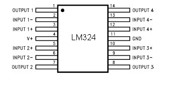
Features
Internally frequency compensated for unity gain
Large DC voltage gain 100 dB
Wide bandwidth (unity gain) 1 MHz (temperature compensated)
Wide power supply range:Single supply 3V to 32V or dual supplies ±1.5V to ±16V
Very low supply current drain (700 μA)—essentially
independent of supply voltage
Low input biasing current 45 nA (temperature compensated)
Low input offset voltage 2 mV and offset current: 5 nA
Input common-mode voltage range includes ground
Differential input voltage range equal to the power supply voltage
Large output voltage swing 0V to V+ − 1.5V
30. Lampu otomatis menggunakan photocell (LDR)
This is a photocell circuit for detecting the light intensity. At full light the resistance of the photocell
will be few ten ohms and at darkness it will rise to several hundred
ohms. IC1 Op amp uA741 is wired as a comparator here. At darkness the resistance of photocell
increases and so the voltage at the inverting input of the IC1 will be
less than the reference voltage at the non inverting input. The output
of the IC1 goes to positive saturation and it switches ON the transistor
to activate the relay. By this way the lamp connected through the relay contact glows. The diode D1 works as a freewheeling diode.

Rangkaian Lampu otomatis menggunakan photocell (LDR)
photocell
A light sensor (photodetector) that varies its resistance between its two terminals based on the amount of photons (light) it receives. Used for photographic light meters, automatic on-at-dusk street lights and other light-sensitive applications, it is also called a "light dependent resistor" (LDR) and "photoresistor."
The photocell's semiconductor material is typically cadmium sulfide (CdS), but other elements are also used. Photocells and photodiodes are used for similar applications; however, the photocell passes current bi-directionally, whereas the photodiode is unidirectional.

Gambar photocell
Photocells come in a variety of packages such as this assortment from PerkinElmer. As the photocell receives more photons, the resistance is lowered between the two terminals.
31. Rangkaian Pendeteksi (Sensor) Kelembaban Udara
Dew
ad- versely affects the normal per- formance of sensitive electronic
devices. A low-cost circuit described here can be used to switch off any
gadget automatically in case of excessive humidity. At the heart of the
circuit is an inexpensive (resistor type) dew sensor element. Although
dew sensor elements are widely used in video cassette players and
recorders, these may not be easily available in local market. However,
the same can be procured from authorised service centres of reputed
companies. The author used the dew sensor for FUNAI VCP model No. V.I.P.
3000A (Part No: 6808-08-04, reference no. 336) in his prototype. In
practice, it is observed that all dew sensors available for video
application possess the same electrical characteristics irrespective of
their physical shape/size, and hence are interchangeable and can be used
in this project.

Skema Rangkaian Pendeteksi (Sensor) Kelembaban Udara
The circuit is basically a switching type circuit made with the help of
a popular dual op-amp IC LM358N which is configured here as a
comparator. (Note that only one half of the IC is used here.) Under
normal conditions, resistance of the dew sensor is low (1 kilo-ohm or
so) and thus the voltage at its non-inverting terminal (pin 3) is low
compared to that at its inverting input (pin 2) terminal. The
corresponding output of the comparator (at pin 1) is accordingly low and
thus nothing happens in the circuit. When humidity exceeds 80 per cent,
the sensor resistance increases rapidly. As a result, the non-inverting
pin becomes more positive than the inverting pin. This pushes up the
output of IC1 to a high level. As a consequence, the LED inside the
opto-coupler is energised. At the same time LED1 provides a visual
indication. The opto-coupler can be suitably interfaced to any
electronic device for switching purpose. Circuit comprising diode D2,
resistors R5 and R6 and capacitor C1 forms a low-voltage, low-current
power supply unit. This simple arrangement obviates the requirement for a
bulky and expensive step-down transformer.
32. Rangkaian Pendeteksi|Sensor Ketinggian Level Air
This is the circuit diagram of a simple Water level detection (Pendeteksi|Sensor Ketinggian Level Air) for home and industries. In fact the the level of any conductive non corrosive liquids can be measured using this circuit. Pendeteksi|Sensor Ketinggian Level Air is based on 5 transistor switches.Each transistor is switched on to drive the corresponding LED , when its base is supplied with current through the water through the electrode probes.
One electrode probe is (F) with 6V AC is placed at the bottom of tank. Next probes are placed step by step above the bottom probe. When water is rising the the base
of each transistor gets electrical connection to 6V AC through water
and the corresponding probe. Which in turn makes the transistors conduct
to glow LED and indicate the level of water. The ends of probes are connected to corresponding points in the circuit as shown in circuit diagram.
Insulated Aluminum wires with end insulation removed will do for the
probe. Arrange the probes in order on a PVC pipe according to the depth
and immerse it in the tank. AC voltage is use to prevent electrolysis at
the probes. So this setup will last really long. I guarantee at least a 2 years of maintenance free operation.That’s what I got and is still going.

Skema Rangkaian Sensor Ketinggian Level Air
list Components of Water level Detection
- T1 - T5 BC 548 or 2N2222
- R1-R5 2.2K 1/4 W
- R6-R10 22K 1/4 W
- D1 - D5 LED’s
Use a transformer 6V 500 mA for power supply. Do not use a rectifier! we need pure AC. Use good quality
insulated Aluminum wire for probes. If Aluminum wires are not available
try Steel or Tin. Copper is the worst. Try the circuit first on a bread
board and if not working properly, make adjustments with the resistance
values . This is often needed because conductivity of water changes
slightly from place to place.
33. Rangkaian Pendeteksi obyek Dengan Infra Red
because the infra red is not visible by naked eye so the idea arose to create a tool pendeteksi movement using infra red this
in the image below is the following circuit diagram of an infrared motion detector that can be used to sense intrusions. Infra red rays reflected from a static object will be in one phase, and the rays reflected from a moving object will be in another phase.The circuit uses this principle to sense the motion.
 Skema Rangkaian Pendeteksi obyek Dengan Infra Red
how to work a circuit of Pendeteksi obyek Infra Red
NE 555 is wires as an astable multivibrator . IR diode connected at the output of this IC produces infrared beams of frequency 5Khz. These beams are picked by the photo transistor Q1 . At normal condition ie; when there is no intrusion the output pin (7) of IC2 will be low. When there is an intrusion the phase of the reflected waveforms has a difference in phase and this phase difference will be picked by the IC2. Now the pin 7 of the IC 2 goes high to indicate the intrusion. An LED or a buzzer can be connected at the output of the IC to indicate the intrusion.
Note:
- Comparators IC2a and IC2b are belonging to the same IC2 (LM1458).
- When there is disturbance in the air or vehicles passing nearby, the circuit may get false triggered.
- POT R5 can be used for sensitivity adjustment
34. Rangkaian Pendeteksi Air Hujan sederhana
circuit of rain detector uses a sensor made of a small piece of etched PC board and a simple SCR circuit to detect rain and sound a buzzer. The SCR could also be used to activate a relay, turn on a lamp, or send a signal to a security system.

Component list of rain detector
- R1 1K 1/4 W Resistor
- R2 680 Ohm 1/4 W Resistor
- D1 1N4001 Silicon Diode
- BZ1 12V Buzzer
- S1 SPST Switch
- SCR1 C106B1 SCR 106CY
- SENSOR
Make sure to use a loud buzzer.
35. Rangkaian Alat Bantu Pendengaran
This circuit, connected
to 32 Ohm impedance mini-earphones, can detect very remote sounds.
Useful for theatre, cinema and lecture goers: every word will be clearly
heard. You can also listen to your television set at a very low volume,
avoiding to bother relatives and neighbors. Even if you have a
faultless hearing, you may discover unexpected sounds using this device:
a remote bird twittering will seem very close to you.
 Skema Rangkaian Alat Bantu Pendengaran
The heart of the circuit is a constant-volume control amplifier. All the signals picked-up by the microphone are amplified at a constant level of about 1 Volt peak to peak. In this manner very low amplitude audio signals are highly amplified and high amplitude ones are limited. This operation is accomplished by Q3, modifying the bias of Q1 (hence its AC gain) by means of R2.
A noteworthy feature of this circuit is 1.5V battery operation.
List Component
P1        : 22K   Log. Potentiometer
R1,R9     : 10K
R2        : 1M
R3        : 4K7
R4,R7     : 100K
R5        : 3K9
R6        : 1K5
R8        : 100R
C1,C2     : 100nF
C3,C6     : 1µF/63V
C4        : 10µF/25V
C5        : 470µF/25V
D1        : 1N4148
Q1,Q2,Q3  : BC547
Q4        : BC337
MIC1      : electret microphone
SW1       : SPST Switch
J1        : Stereo 3mm. Jack socket
B1        : 1.5V Battery (AA or AAA cell etc.)
36. Microphone Condenser Pre Amplifier Circuit
This is a simple preamplifier circuit for electret condenser microphone. using a LM1458 dual op amp IC. The circuit takes the audio signal rom the condenser
microphone and amplifier it, so you can use the microphone as the input
to some device which wouldn’t normally accept microphone level signals .

The
circuit requires a 6-9 volt supply. Output of the microphone
amplifier can be made variable by connecting a 10kΩ potentiometer .
Circuit’s gain can be increased by men perbesar the value of 47K,
depending on the input sensitivity of the main amplifier system. The
microphone should be housed in a small round enclosure.
R1,R2,R3 : 4.7k ohm resistor
R4, R5 : 10k ohm resistor
R6,R7 : 47k ohm resistor
C1, : 0.22uF ceramic capacitor
C2 : 1uF ceramic capacitor
 Absolute maximum ratings of LM 1458 IC
Supply Voltage : ±18V
Power Dissipation : 400 mW
Differential Input Voltage : ±30V
Input Voltage : ±15V
Output Short-Circuit Duration: Continuous
Operating Temperature Range : 0°C to +70°C
Storage Temperature Range : −65°C to +150°C
Lead Temperature :(Soldering, 10 sec.) 260°C
37. Rangkaian Op-Amp (LM741) Pre-Amp Mic
This is the circuit of Op-Amp Microphone Preamplifier using a single power supply, this circuit suitable for dynamic or electret microphones. Nothing too special here. The Schematic is shown using a dynamic microphone, for use with an electret a pair of suitable biasing resistor is required to power the electret microphone.
 Skema rangkaian op-amp pre-amp mic
Note:
- use a capacitor with voltage 25volt or more
- so that the sound produced maximal use supplay good voltage, with output of 18 volts max
- If the desired strengthening of the different, you can change the value of R1 or R2
The design is a standard non-inverting design, the input is applied to the non-inverting input of the op-amp, which is pin 3 in most cases. The input impedance is 23.5k, the overall voltage gain is determined by R2 and R1according to the following formula:
Vo = (R2 / R1) + 1
With the values of R2 and R1 on the diagram of the voltage gain (for mid band, 1kHz) is approximately 23x or 27.2dB.
Pinning IC Op-Amp LM741

38. Rangkaian Audio Mixer 6 Channel
Audio Mixer 6 Channel
The following is a main of the mixer-6 Ch circuit. The circuit constituted by six input channels. The channels are from monophonic channels CH 1-4 and CH 5-6, are intended for stereo use. The number of input channels they want as long Itself Can Increase You Want.
The following is a main of the mixer-6 Ch circuit. The circuit constituted by six input channels. The channels are from monophonic channels CH 1-4 and CH 5-6, are intended for stereo use. The number of input channels they want as long Itself Can Increase You Want.
 Skema rangaian audio mixer 6 channel
The output of Each channel drives the RV1-6, that regulation potesometer level of sound. With RV7-12 We create conditions of balance Between two channels (BALANCE). All the signals from the input channels in this point are added by two adders [IC1a-b], for Each channel Here exist two Trimmer TR1-2 That adjust the gain of Each IC, adapting the level of signal of the output, in the level That We Want. They Can be suppressed if you do not need something and Standard and Poor. The next stage is a equalizer, three bands of regulation. The IC3α-b, constitute the output of the mixer, they want a one acre have gain and they want the make the essential isolation of the previous stages, with the unit That We Will drives. For whoever they want want they want use headphones, it exists a classic circuit drive of headphones, round the IC2a-b, that give the output in the JF13. It Can Also Also exist optical clue of audio levels, with a stereo VUMETER.
List component
- R1-12=4.7Kohms
- R13-24=10Kohms
- R25-26=22Kohms .
- R27-30-34-39=100ohms
- R28-29-36-37=100Kohms
- R31-42=10Kohms
- R32-41=4.7Kohms
- R33-40=10Kohms
- R35-38=47ohms
- RV1....4=47Kohms Log.
- RV5-6-13=2X47Kohms Log.
- RV7....12=10Kohms Lin. pot. Log
- C1....8=10uF 25V
- C9-11=47pF ceramic or mylar
- C10-12=47uF 25V
- C13-14=100uF 25V
- C15-16=2.2uF 16V
- C18-21=100pF ceramic or mylar
- C19-20=220uF 25V
- TR1-2=4.7Kohms trimmer
- Q1-3=BD139
- Q2-4=BD140
- IC2=NE5532 - TL072
39. Microphone Komputer
The sound card for a PC generally has a microphone input, speaker output and sometimes line inputs and outputs. The mic input is designed for dynamic microphones only in impedance range of 200 to 600 ohms. Lazar has adapted the sound card to use a common electret microphone using this circuit. He has made a composite amplifier using two transistors.
 Skema rangkaian microphone komputer
Transistor BC413B operates in common emitter to give a slight boost to the mic signal. This is followed by an emitter follower stage using transistor BC547C. This is necessary as the mic and circuit and battery will be some distance from the sound card, the low output impedance of the circuit and screened cable ensuring a clean signal with minimum noise pickup.
Transistor BC413
- Collector Emitter Voltage VCEO 30 V
- Collector Base Voltage VCBO 45 V
- Emitter Base Voltage VEBO 5.0 V
- Collector Current Continuous IC 100 mA
- Power Dissipation at Ta=25ºC PD 350 Mw Derate Above 25ºC 2.8 mW/ºC
- Power Dissipation at Tc=25ºC PD 1.0 W Derate Above 25ºC 8.0 mW/ºC
- Operating and Storage Junction TJ, Tstg ºC - 55 to +150
Transistor BC547C
- Collector-Base Voltage VCBO (IE = 0) 50 V
- Collector-Emitter Voltage VCEO (IB = 0) 45 V
- Emitter-Base Voltage VEBO (IC = 0) 6 V
- Collector Current IC 100 mA
- Collector Peak Current ICM 200 mA
- Total Dissipation at Ptot TC = 25 oC 500 mW
- Storage Temperature Tstg -65 to 150 oC
- Operating Junction Temperature Tj Max. 150 oC
40. Rangkaian Pre-Amp Mic Condenser
Microphone amplifier circuit is simple, consisting of 2 levels. with wide dynamic regions, small noise, and can with a long cable about 50 meters.
all capacitor (elco) using 25-voltto avoid the buzzing sound, use a good regulator supplayThis circuit can provide voltage 6-20volt

This circuit uses low noise transistors are type types: BC 650 C but the transistor is hard to find, so you can replace it with 109 BC is no less good. This condenser mic element in it is a very sensitive microphone, and to use this mic condenser required voltage between 2-10 volts, for that we can resistors in series with 1K-10 K ohms, in the picture above the tide 1k ohms
Pin BC109
- Emitter
- Base
- ollector, connected to the case
BC109 limiting values
collector-base voltage 30 V
collector-emitter voltage 20 V
emitter-base voltage 5 V
collector current (DC) 100 mA
peak collector current 200 mA
peak base current 200 mA
total power dissipation Tamb £ 25 °C - 300 mW
storage temperature 65 +150 °C
junction temperature 175 °C
operating ambient temperature -65 +150 °C
DC current gain (hFE) IC = 10 mA; VCE = 5 V 100 -- 270
41. Rangkaian Pre-Amp Mic 2 Transistor.
Here is a Pre-amp microphone dynamic using two transistors. The circuit factor of this around 150 and can handle signals from 50Hz to 100Khz.This circuit is designed for use with 200 Ohm dynamic microphones. For usage with low impedance microphones, the value of R3 must be increased to around 47o Ohms and C1 must be decreased to around 2.2uF.

The audio signal from the microphone is coupled to the base of Q1 via the capacitor C1 and resistor R3. Q1 works as a preamplifier
here. The preamplified signal will be coupled to the base of Q2 for
further amplification. Resistor network comprising of R4, R5 and R6
provides the necessary negative feedback. Final output signal will be available at the emitter of Q2.
Layout Transistor BC549 & BC546
Transistor BC549 Absolute maximum rating
- VCBO collector-base voltage open emitter...............30 V.
- VCEO collector-emitter voltage open base...............30 V.
- VEBO emitter-base voltage open collector................5 V.
- IC collector current (DC)........................................100 mA.
- ICM peak collector current......................................200 mA.
- IBM peak base current............................................200 mA.
- Ptot total power dissipation Tamb £ 25 °C..................500 mW.
- Tstg storage temperature...................................... -65 to +150 °C.
- Tj junction temperature..........................................150 °C.
- Tamb ambient temperature..................................... -65 to +150 °C.
- hFE DC current gain VCE = 5 V, IC = 2 mA .............420 to 800.
Transistor BC546 Absolute maximum rating
- VCBO collector-base voltage open emitter..................80 V.
- VCEO collector-emitter voltage open base..................65 V.
- VEBO emitter-base voltage open collector..................6 V.
- IC collector current (DC).........................................100 mA.
- ICM peak collector current.......................................200 mA.
- IBM peak base current.............................................200 mA.
- Ptot total power dissipation Tamb £ 25 °C.................. 500 mW.
- Tstg storage temperature........................................ -65 +150 °C.
- Tj junction temperature...........................................150 °C.
- Tamb operating ambient temperature ........................-65 +150 °C.
- hFE DC current gain VCE = 5 V, IC = 10 mA..............150.
42. Hifi stereo pre-amp head
This is hifi stereo pre-amp head with tone control circuit Using a special IC TDA1524A
All signal processing is done within the TDA1524A by voltage controlled amplifiers and voltage controlled filters. The IC provides a fixed voltage (~ 3.8V DC) at pin 17, and this is used by all the variable resistors to provide an adjustable DC voltage to the appropriate control pins.
Current sensing is used to provide a flat response when R5 is connected to pin 17, and a loudness contour when disconnected. 100 nF capacitors are used on each pot to decouple any AC signals from the control inputs. 10 uF capacitors are used to couple both input and output audio signals whilst blocking DC. R1 and R2, are to ensure stability with capacitive loads. R3 and R4 make sure there are no DC spikes at the output sockets if the load is switched. C3 and C4 control the loudness contour. C5 and C6 control the treble turn-over frequency. C18 and C19 have been added to roll off the gain above 70 kHz. Low volume settings coupled with treble boost was causing HF instability in some instances. This should no longer be a problem.
 Skema rangkaian hifi stereo pre-amp head
C15, 16, 17 provide power supply filtering. D1 provides protection in case of incorrect supply polarity. The LED is a power on indicator and may be omitted if not required, or preferably mounted on the enclosure. If you are not using a switch pot, you can connect an external switch across the P1 switch pins, or connect a wire link there and switch the power supply.
The power supply is critical to the noise performance of the pre-amp head. An on board regulator is provided to reduce mains hum. If you wish to use it with a car or other 12V battery, then you should omit the 7812 regulator, and place a wire link between the regulator input and output pin positions on the PC board. Do not short to earth! This will be necessary because the regulator must have an input voltage at least 2-3V greater than it’s output, for it to maintain regulation. However the regulator will not be necessary with a battery supply.
If using a plug pack, it’s output voltage should be 15 to 18V DC. Because most plug packs have poor regulation, one rated at 12V DC will often be around 15V when lightly loaded. The current drain of the pre-amp is less than 50 mA, so many 12 V unregulated supplies may be adequate if you have one. Replace D1 with a wire link if necessary, making sure you have the supply polarity correct!
If you are using a 15-20V supply for your power amplifier, you can use that as your pre-amp supply as well. Make sure you test the voltage first in all cases.
43. Rangkaian Pre- Amp mic 3 input - lm741
This is a 3 input mic mixer circuit
using IC LM 741. Four 741s are used here. IC1, IC2, IC3 are used as
preamplifiers. They produce a gain of around 40 decibel to the individual
input signals. IC4 is wired as a summing amplifier to add the signals
from three preamplifiers.IC4 also gives a gain of around 5 decibel to
the final output signal. Total gain of the system is around 45 decibel.
Note:

• Use+15/-15 V DC dual power for powering this circuit.
• All inputs and output must be connected with respect to the ground.
• Capacitors C1, C2 and C3 must be rated 10V and other capacitors must be 30V.
General Description

Lay out IC LM 741
The LM741 series are general purpose operational amplifiers which feature improved performance over industry standards like the LM709. They are direct, plug-in replacements for the 709C, LM201, MC1439 and 748 in most applications. The amplifiers offer many features which make their application nearly foolproof: overload protection on the input and output, no latch-up when the common mode range is exceeded, as well as freedom from oscillations. The LM741C is identical to the LM741/LM741A except that the LM741C has their performance guaranteed over a 0°C to +70°C temperature range, instead of −55°C to +125°C.
44. Rangkaian Microphone/Mic FM Wireless
Microphone/Mic FM Wireless is basically an FM transmitter to low power. FM Wireless Mic circuit you can use it to replace the wireless mic is usually quite expensive price.
If you are a fan of electronics, then the series is worth your trying,
but its component prices cheaper tool is also very useful. Here is a picture of his series:
 Skema Rangkaian Microphone/Mic FM Wireless
List Component of Microphone/Mic Wireless
1 = 10K (brown-black-orange)
R2,R3 = 100K (brown-black-yellow)
R4 = 470 ohm (yellow-violet-brown)
C1,C3 = 4.7pF (4p7), ceramic
C2,C4 = 4.7uF-16V, electrolytic
C5 = 0.001uF (1nF), ceramic
C6 = 470pF, ceramic
Q1,Q2 = 2N2222, NPN transistor
L1 = 1uH, variable inductor
Mic = Electret mike, 2 wires
Q1 amplifies the input signal via C4 from the electret microphone. Q2 acts as an oscillator and the signal coming off C2 is fed onto the base of Q2. L1/C1 is a so called ‘tank’ circuit and operates in the 88-105MHz band on your regular AM/FM radio dial.
L1 is a 1uH variable inductor coil to be able to tune it a little bit, and the range of 1uH is approximate. The antenna can be as simple as a 8″ (21cm) piece of wire of any kind
45. Rangkaian Audio Mixer 3 Input
Many audio mixer circuits have been published but this this very simple audio mixer circuit uses only one transistor. The base emitter junction of the transistor is biased by the diodes D1 and D2.The signals to be mixed are directly coupled to the base
of Transistor. Each input lines are current limited by using a 10k
Potensiometer . With the used component values the collector current is
around 1mA.
 Skema Rangkaian Audio Mixer 3 Input
Notice:
- The circuit can be assembled on a Vero board.
- The circuit can be powered from 9-25V DC.
- of each channel can be set using Variable resistor 10k
Transistors in the following series is enabled as a source of constant flow. By providing input audio signal on the emitter, the voltage on the emitter will fluctuate, which will cause the collector voltage also fluctuates. The amount of frequency fluctuation is comparable with the frequency of the incoming audio signal.
46. Circuits of audio pre-Amp mic
A microphone preamp is a preamplifier used to amplify a microphone's low output voltage to a stronger, more usable level. A microphone preamp must provide stable gain for small
signals without being sensitive to induced noise from cabling and
without distorting large amplitude signals. Most microphones must be
used in conjunction with a microphone preamp to function properly.
Simple audio Pre-Amp mic

 This circuits use infront an RF oscilator to make an RF transmitter that is very sensitive to sound
47. Rangkaian Infra Red Remote Tester
The circuit is very effective to test the remote controls what still works or not, the remote record will be tested using infra red. Examples of the TV remote, AC and others. Please try I am sure 100% will be successful.
 Rangkaian Remote Tester
The workings of the circuit is very simple, when the infra red sensor receive infrared signals pin 2 sensor will produce a voltage, this voltage will drives the PNP transistor so that the LED lamp and piezo disc (BZ) is active. for the power supply you can use a 9 volt battery and then use IC 7805 or use 1.5 volt batteries x 3
Following the specification of components installed
- Transistor BC557
- TSOP 1738 Sensor Infra Red
- R1 = 10k ohm ¼ watt Resistor
- R2 = 1k ohm ¼ watt Resistor
- R3 = 1k ohm ¼ watt Resistor
- BZ = piezo disc
- led

Features
- Photodetector and preamplifier circuit in the same casing.
- Receives and amplifies the infrared signal without any external component.
- 5 V output (active at level 0).
- 38 kHz integrated oscillator.
- High sensitivity.
- High level of immunity to ambient light.
- Improved shielding against electrical field interference.
- TTL and CMOS compatibility.
- Applications: infrared remote control.
- Supply: 5 V
- Power consumption: 0.4 to 1.0 mA
- Min. Ee irradiation: 0.35 mW/m2 typ.
- Angle of detection: 90
- Dimensions of the casing (mm): 12.5 x 10 x Thickness 5.8
- Temperature range: -25 C to +85 C
48. Rangkaian Remote Control Ultrasonic
This is a remote control circuit employing ultrasonic signals. The ultrasonic transmitter circuit
is build around IC1(NE 555). IC1 is an astable multi vibrator operating
at 40KHz.The output of IC1 is amplifier the complementary pair of transistors ( Q1 & Q2) and transmitted by the ultrasonic transmitter K1. The switch S1 is used activate the transmitter.

Note:
- switch S1 can be a push button switch.
- The preset R16 can be used to adjust the sensitivity of the receiver.
- The frequency of the ultrasonic signal can be varied by adjusting the preset R17.Adjust it for optimum performance.
The ultrasonic receiver uses an sensor transducer (K2) to sense the ultrasonic signals. When an ultrasonic signal is falling on the sensor, it produces a proportional voltage signal at its output. This weak signal is amplified by the two stage amplifier circuit comprising of transistors Q3 and Q4.The output of the amplifier is rectified by the diodes D3 & D4.The rectified signal is given to the inverting input of the opamp which is wired as a comparator. When ever there is an ultrasonic signal falling on the receiver, the output of the comparator activates the transistors Q5 & Q6 to drive the relay. In this way the load connected via the relay can be switched. The diode D5 is used as a free wheeling diode.
Features IC CA3140

- Very High Input Impedance (ZIN) -1.5TΩ (Typ)
- Very Low Input Current (Il) -10pA (Typ) at ±15V
- Wide Common Mode Input Voltage Range (VlCR) - Can be wung 0.5V Below Negative Supply Voltage Rail
- Output Swing Complements Input Common Mode
- Directly Replaces Industry Type 741 in Most Applications
- Pb-Free Plus Anneal Available (RoHS Compliant)
Pin Connection Ic NE 555

- Ground, is the input pin of the source of the negative DC voltage
- Trigger, negative input from the lower comparators (comparator B) that maintain oscillation capacitor voltage in the lowest 1 / 3 Vcc and set RS flip-flop
- Output, the output pin of the IC 555.
- Reset, the pin that serves to reset the latch inside the IC to be influential to reset the IC work. This pin is connected to a PNP-type transistor gate, so the transistor will be active if given a logic low. Normally this pin is connected directly to Vcc to prevent reset
- Control voltage, this pin serves to regulate the stability of the reference voltage negative input (comparator A). This pin can be left hanging, but to ensure the stability of the reference comparator A, usually associated with a capacitor of about 10nF to berorde pin groun
- Threshold, this pin is connected to the positive input (comparator A) which will reset the RS flip-flop when the voltage on the capacitor from exceeding 2 / 3 Vc
- Discharge, this pin is connected to an open collector transistor Q1 is connected to ground emitternya. Switching transistor serves to clamp the corresponding node to ground on the timing of certain
- Vcc, pin it to receive a DC voltage supply. Usually will work optimally if given a 5-15V. the current supply can be seen in the datasheet, which is about 10-15mA.
49. Rangkaian Remote Control IC 555
Remote Control menggunakan IC 555
Ic 555 is an integrated circuit (chip) implementing a variety of timer and multivibrator applications. The IC was designed by Hans R. Camenzind in 1970 and brought to market in 1971 by Signetics (later acquired by Philips). The original name was the SE555 (metal can)/NE555 (plastic DIP) and the part was described as "The IC Time Machine". It has been claimed that the 555 gets its name from the three 5-kohm resistors used in typical early implementations, but Hanz Camenzind has stated that the number was arbitrary The part is still in wide use, thanks to its ease of use, low price and good stability. As of 2003 it is estimated that 1 billion units are manufactured every year.
Ic 555 is an integrated circuit (chip) implementing a variety of timer and multivibrator applications. The IC was designed by Hans R. Camenzind in 1970 and brought to market in 1971 by Signetics (later acquired by Philips). The original name was the SE555 (metal can)/NE555 (plastic DIP) and the part was described as "The IC Time Machine". It has been claimed that the 555 gets its name from the three 5-kohm resistors used in typical early implementations, but Hanz Camenzind has stated that the number was arbitrary The part is still in wide use, thanks to its ease of use, low price and good stability. As of 2003 it is estimated that 1 billion units are manufactured every year.
Depending on the manufacturer, the standard 555 package includes over 20 transistors, 2 diodes and 15 resistors on a silicon chip installed in an 8-pin mini dual-in-line package (DIP-8).
The 556 is a 14-pin DIP that combines two 555s on a single chip. The 558 is a 16-pin DIP that combines four slightly modified 555s on a single chip (DIS & THR are connected internally, TR is falling edge sensitive instead of level sensitive).
Also available are ultra-low power versions of the 555 such as the 7555 and TLC555. The 7555 requires slightly different wiring using fewer external components and less power.
 Skema Rangkaian Remote Control IC 555
The connection of ic 555 as follows:
- GND(1)Ground, low level (0V)
- TRIG(2)A short pulse high-to-low on the trigger starts the timer
- OUT(3)During a timing interval, the output stays at +VCC
- RESET(4)A timing interval can be interrupted by applying a reset pulse to low (0V)
- CTRL (5)Control voltage allows access to the internal voltage divider (2/3 VCC)
- THR (6)The threshold at which the interval ends (it ends if U.thr → 2/3 VCC)
- DIS (7)Connected to a capacitor whose discharge time will influence the timing interval
- V+, VCC(8) The positive supply voltage which must be between 3 and 15 V
50. Rangkaian Radio Remote Control Mobil Mainan
Rangkaian Remote Control Mobil Mainan
In this system, radio signals emanated not continue to be raised but only when the controller sends the right / left or forward / backward, that is only a radio frequency that discontinuous,so that the credit delivery frequency radio waves.
The amount of credit that is sent to represent the command post, the forward was represented with 8 credits, left represented with 16 credits, 32 credits right and Backward 64 credits. Commands can be sent is a combination of 2 commands, namely the combination of forward / backward and right / left, as an example can be sent forward and the left, in this case the amount of credit that is sent 24, the Answer of the forward and the balance of 8 the left as many as 16 credits.
 Skema Rangkaian Pemancar Radio Remote Control
 Skema Rangkaian Penerima Radio Remote Control
 Making transformer TX and RX:
Transformer
T1 in series transmitter and recipient, is the same, and must be made.
Transformer was built using plastic koker transformer (spare part radio)
so that the step appears to have 5 channels that can be filled with a
wire coil, as shown in the picture.
Wearing this koker facilitate scrolling wire transformer. If it can not
be koker like that, just use the normal. Koker transformer is small and ferit is also small (3 mm) as the first assembly is often used for CB 27 MHz radio.
Transformer wire to wire to use in the unloading of koker, and slowly open the wire coil inside the existing wire koker because it is quite smooth and easy to drop out
- coil wire from the foot of the number to 5 feet 4 hours direction (CW) of 3-and-roll at level 1 (line at the bottom line above)
- Scroll through the wire from 1 foot to 2 feet clockwise roll of 4 on the exact level 2.
- Continue to roll (from step 2) clockwise a quarter roll of 3 to 3 feet in three levels. (You can set exactly a quarter roll, because the path that has kokernya be split into 4).
Scroll through the copper wire diameter size of 0.3 - 0.5 mm of 10 quarter roll koker in diameter about 4 mm (which will be released later) is also clockwis
Making coil L2
Scroll through the copper wire diameter of 0.1 mm sizes of 50 on the roll without koker plastic ferit diameter about 3.5 - 4 mm (search item from the plastic material used) is also clockwise. The length of the coil along liputi in 5 mm
51. Remote Control infra Merah Sederhana

Skema Rangkaian Remote Control Transmitter
As mentioned above, the remote control must have the same frequency with the frequency transmitted by the transmitter chain. Recipient of this frequency range can be determined with the following equation:


Skema Rangkaian penerima Remote Control
To simplify the process of tunning, R1 at the recipient install a remote control in the variable resistor (VR). while the transmitter constant value (resisitor tetep / normal). If a circuit of remote control has been completed on the raft, to know whether a circuit of working well, the first step must be done is make tunning, with the transmitter is turned on continuously, while R1 is set so that the recipient can detect the signal transmitter. If the tuning is successful, the relay recipient akan romote control switch position (nye-Tech), when it has happened means that a circuit of remote control is working well. to the next can try pressing the switch on the remote control at the sender (transmitter). should switch on when the press kutup relay at the remote recipients will move kutup (nye-Tech)